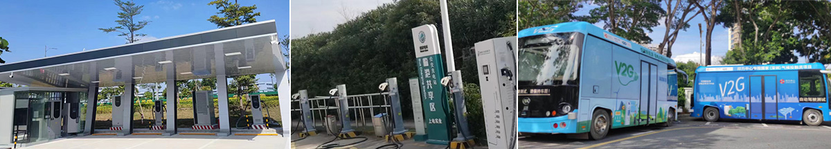
V2G is an abbreviation for Vehicle to Grid. As the name implies, it describes the interaction between electric vehicles and the grid: when the electric vehicle is not in use, the power from the on-board battery is sold to the grid system. If the on-board battery needs to be charged, current flows from the grid to the vehicle.
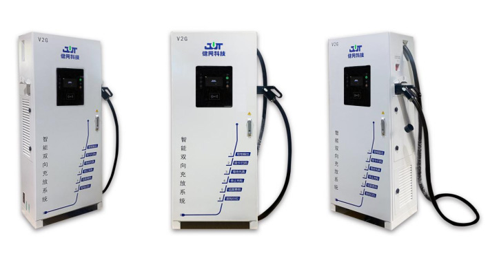
The V2G charger uses electric vehicle power batteries as distributed energy storage devices, and through an energy management system, it completes the balance and optimization of power supply and power demand between the power grid and electric vehicles. It brings application value in peak and valley power consumption, distribution network capacity expansion, user side energy storage, battery detection, and other aspects. It can also serve as a core node to achieve smart grid access and supplement user side energy storage.
V2G technical parameters:
|
Charging mode parameters
|
|
Rated output power
|
80kW
|
|
Grid side voltage
|
380Vac±15%(Three phase)
|
|
Grid frequency
|
50Hz±5Hz
|
|
DC side output voltage
|
200~750Vdc
|
|
Constant power range
|
400~750Vdc
|
|
DC side output current
|
Single gun maximum 200A
|
|
Inverter mode parameters
|
|
Rated output power
|
80kW
|
|
DC side input voltage
|
200~750Vdc
|
|
Grid side voltage
|
380Vac(Three phase)
|
|
Grid frequency
|
50Hz±5Hz
|
|
system parameter
|
|
THDI
|
<5%(Full load)
|
|
Power factor
|
±-0.99(Full load)
|
|
Productiveness
|
≥95%(Full load)
|
|
Wiring mode
|
3P3W
|
|
noise
|
≤65 dB
|
|
Cooling method
|
forced air cooling
|
|
Power distribution
|
Support
|
|
Number of charging guns
|
Single gun, double gun
|
|
Protection level
|
IP54
|
|
Communication interface
|
Ethernet, 4G
|
|
Display
|
7-inch touch screen
|
|
DC output characteristics
|
|
Output voltage range
|
200 V~750 V
|
|
Output current range
|
Single gun maximum 200A
|
|
Voltage stabilization accuracy
|
Not more than ± 0.5% (stabilized state, input voltage AC 323 V to 456 V, output voltage 200 V to 750 V, output current 0 to rated current value)
|
|
Steady current accuracy
|
Not more than ± 1% (steady current state, input voltage AC 323 V to 456 V, output voltage 200 V to 750 V, output current 20% of rated current to rated current value)
|
|
Voltage ripple factor
|
Not more than 1% (in stable state, the input voltage is AC 323 V to 456 V, the output voltage is 200 V to 750 V, and the output current is 0 to the rated current value)
|
|
Output voltage setting error
|
Not more than ± 0.5% (stabilized state, output voltage 200 V to 750 V)
|
|
Output current setting error
|
Not exceeding ± 0.3 A (set output DC current < 30 A)< br />
Not more than ± 1% (steady current state, set output DC current ≥ 30 A)
|
|
Voltage limiting characteristics
|
During steady current operation, when the DC output voltage exceeds the set value, the automatic limit output voltage increases and switches to steady state
|
|
Current limiting characteristics
|
During steady state operation, when the DC output current exceeds the set value, the automatic limit output current increases and changes to steady state
|
|
Maximum efficiency
|
≥95%
|
|
Protection features: input overvoltage and undervoltage protection, input overcurrent protection, output overvoltage and undervoltage protection, overtemperature protection, etc
|
Energy storage+V2G fusion scheme:
The system is mainly composed of low-voltage power distribution, current sampling transformer, EMS energy management system, V2G charger, energy storage converter, energy storage battery, etc.
Through the EMS energy management system, stable operation between the V2G system and the energy storage system can be achieved without reverse power transmission to the grid side. According to the usage requirements, the following system working modes can be realized:
Use existing mains power (no more than 80kW) to charge electric vehicles through V2G chargers;
Using existing mains power (not exceeding 80kW, including when simultaneously charging V2G), charge the energy storage battery through the energy storage converter;
When discharging an electric vehicle, charge the energy storage battery;
When the energy storage battery has sufficient capacity, charge the electric vehicle.
Charging measures
1) The V2G charger can accept commands from the background monitoring system or local code scanning and card swiping commands to initiate charging operations. During the charging process, the communication protocol between the V2G charger and the electric vehicle BMS complies with the standard GB/T 27930-2015 "Communication Protocol between Offboard Conductive Charging and Discharging Motors and Battery Management Systems for Electric Vehicles.".
2) The V2G charger can manually set charging parameters through the touch screen to charge the power battery.
Discharge measures
1) The V2G charger can accept commands from the background monitoring system or the electric vehicle BMS to start the discharge operation and feed back the power battery energy to the microgrid. During the discharge process, the communication protocol with the electric vehicle BMS shall comply with the standard GB/T 27930-2015 "Communication Protocol between Offboard Conductive Charging and Discharging Motors and Battery Management Systems for Electric Vehicles".
2) The V2G charger can manually set the discharge parameters through the touch screen to feed back the power battery energy to the microgrid system.
3) By cooperating with a countercurrent prevention device, it is possible to ensure that the entire system's discharge power does not backflow to the grid, allowing the electric energy released by the electric vehicle battery to be consumed within the microgrid system.